A machinist's hammer with two different soft heads would be nice to have and seems like a nice tool to make during the Covid-19 isolation. The hammer will be made with at least two soft replaceable faces. Initially, there will be a brass face and a delrin (acetal) face (maybe aluminum in the future). I have a few lengths of 1 3/8" hex aluminum that will be used for the head and the handle. The center part of the head will be left at 1 3/8" since it already has a flat face for handle attachment. Both the head and the handle will need to be made using the South Bend lathe. The three jaw chuck on the Sherline will only hold about 1 1/8" of the stock with the jaws reversed.
The faces will be 1" in diameter and 3/4" long. The head will be 2 1/4" long. Narrow necks will join the 3/8" X 1" face plates to the unaltered hex serving as the center of the head. A rough sketch of the planned head is shown below. The neck will be roughed out with a cutoff tool and then filed to final shape.
Hopefully, the isolation will conclude prior to my planned MASW CAD course. If so, this will be one of the last of the iSketch drawings.
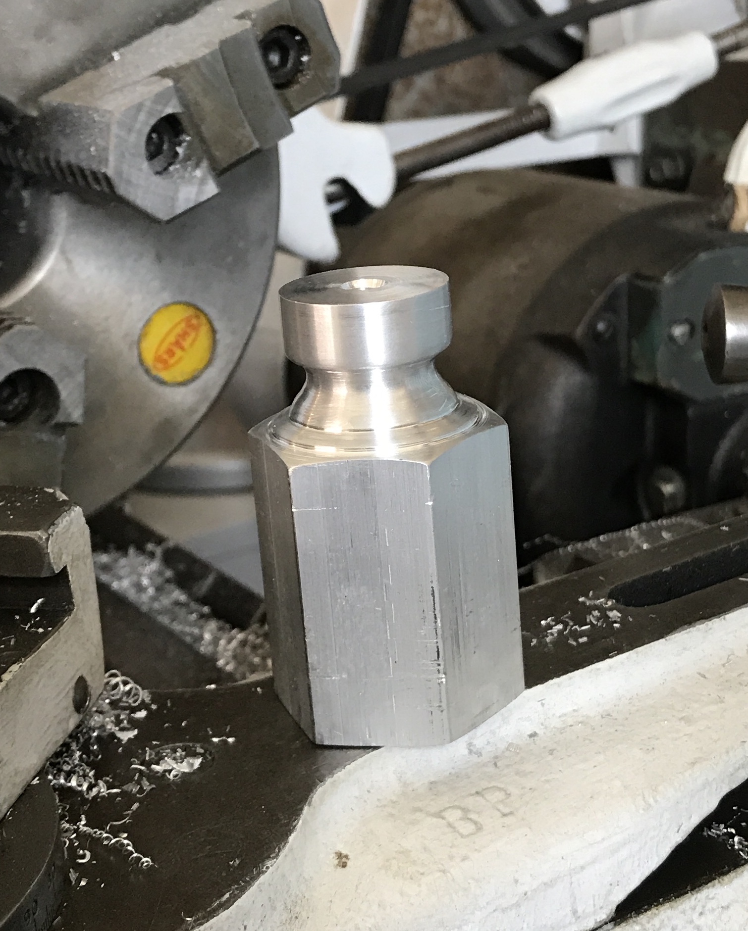
A 5" length of the 1 3/8" aluminum hex was cut with a hacksaw to provide a 3" length of the hex stock. This was chucked in the South Bend lathe leaving a little more than 2 1/4" out. The aluminum was faced and center drilled for a live tailstock center. The first 0.5" was reduced to 1.00" diameter. The parting tool was used to provide steps forming the neck behind the face. This was then filed with a round file and a half round file to produce the desired profile. It was also sanded to 1000 grit. Work was started on the chuck end. A 1/2" length starting 1 3/4" from the free end was reduced to 1 1/8". Work was stopped at this point due to the 50° temperature in the garage.
The face constructed above was drilled with a #7 drill and tapped 1/4-20. The part was removed and reversed in the chuck. The diameter was reduced to 1.00" and then the part was faced so about 3/4" of 1" stock remained. A .25" deep cut was made with the parting tool about 5/16" from the end. Two different tools were used to make the neck. Since, the filing above took about 1 hour a different approach was needed. This approach still needed filing, but significantly less. The two ends are quite different as a result of the different approaches. Oh well, a unique hammer! The end was center drilled, drilled with the #7 drill, and tapped 1/4-20. The next hour was spent cleaning up the aluminum chips.
I have decided to use the end of the handle as a place to store a third soft head, so the three heads will be nylon, brass and aluminum. The handle will be 3" long with a 1/2" transition to a narrower 3 1/2" long neck. The neck will terminate in a 1/2" length of 3/8-16 threads. A few decorative grooves and knurling will finish the handle. The 3" handle is a bit short, but when the third soft head is screwed in place it will be 4" long.
Started on the handle in the 50° garage this morning. A 10" length of 1 3/8" hex was placed in the three jaw chuck. It was center drilled and faced. A live tailstock center was used for support. About 7 3/4" was reduced to 1 1/4" diameter. (A hammer handle was measured and found to be 1 1/4" X 1".) A section 3" to 7 3/4" was then further reduced to 1.0". The compound slide was then used to cut the angle from one diameter to the next. The compound was set at a 45° angle. The cross slide was advanced 0.005" and the compound slide was then advanced to the smaller diameter. Once the angle met the large diameter, one final pass was taken along the small diameter. The small diameter was sanded with 220- and 400-grit paper.
The handle was cut off at 8" with the parting tool. The tailstock center was used during the parting off, but the cutting was stopped with about 1/8" left. The rest was cut with a hacksaw. The handle was then turned around in the chuck and soft jaws were used to hold the large diameter end. The small diameter end was faced and center drilled. 1/2" of this end were reduced to 3/8" while using a tailstock center. The parting tool was used to put a groove for thread relief. A 3/8-24 die was used to thread the reduced end while the handle was held in the vise. The threaded hole for storing the third face will be cut after knurling the handle.
The knurling tool cannot be mounted on the South Bend lathe so the work was moved to the basement. At this point I realized that the knurling tool will not work on the handle. It does not open sufficiently to span the 1 1/4" diameter! Consequently, a knurling tool for the South Bend has been ordered from Victor Machinery. They were the first retail outlet that had an inexpensive knurl holder that would fit the lathe's lantern post.
Spent the morning writing a program to calculate the lathe cuts needed for a round groove in the side of a shaft. A second length of 1 3/8" X 3" hex stock was chucked in the South Bend and the end faced 3/4" was reduced to 1" diameter. A Sharpie mark was made at 1/2" and the 1/16" parting tool was centered on this mark. According to the calculations it was advanced into the shaft 0.118". A series of 18 cuts was then made moving the compound slide to the right (0.010" initially and 0.005" later.) Each cut was shallower than the last. This series of 18 cuts was repeated moving the compound to the left. This produced the rough semi-circular groove seen in the following picture.
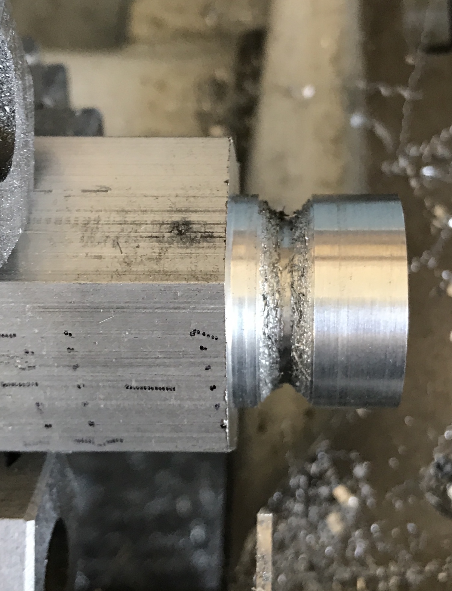
The picture shows a very rough surface, but a few strokes with a 1/4" round file and it was a very nice groove. An additional 1/8" of shaft was reduced to about 1 3/16". The left side of the groove was filed (about 200 strokes with a half round file). Sanding up to 1500 grit produced the following finish. On the other side I may use cuts for a 1/8" radius groove on the right and a 1/4" radius groove on the left. This should eliminate most of the filing and probably produce a better result. Before removing the work from the chuck the end was center drilled and then drilled 1/2" deep with a #7 drill. After removing the hole was tapped 1/4-20.
The hammer head was reversed in the chuck and the end was faced. The first 3/4" was reduced to 1.00". The part was pulled out of the chuck so enough material protruded giving the parting tool in the compound set at 90° sufficient room. The first cut was made 1/2" from the end of the part to a depth of 0.118". This was followed with the series of cuts to the right making a 1/8" radius. The parting tool was returned to the first cut and a series of cuts was made to the left. In this case the compound was adjusted 0.02" and 0.01" instead of the prescribed 0.01" and 0.005", respectively. This led to a wider semi-circular cut. The hex was reduced by about 3/16" for 1/8". Filing gave a decent groove and was followed by sanding to 1500 grit.
The hammer head was then held in a vise on the large drill press. It was very difficult to get any drill to penetrate the aluminum! I guess this is because the speed is too high. When attempting to use a small center drill the tip broke off in the work. I was unable to remove the stub so the part now has a new feature, a round depression on the face opposite the handle. The head was easily drilled on the small drill press with significantly lower speed. It was drilled up to an "O" drill 1/2" deep centered on one face and then tapped 3/8-24. It was sanded on all of the hex faces 150 to 1500 grit.
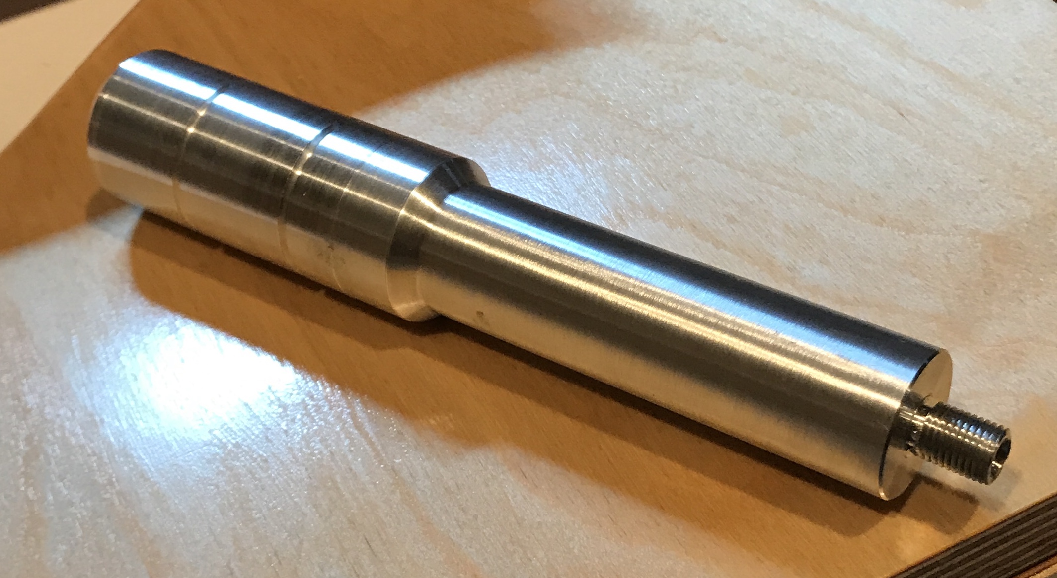
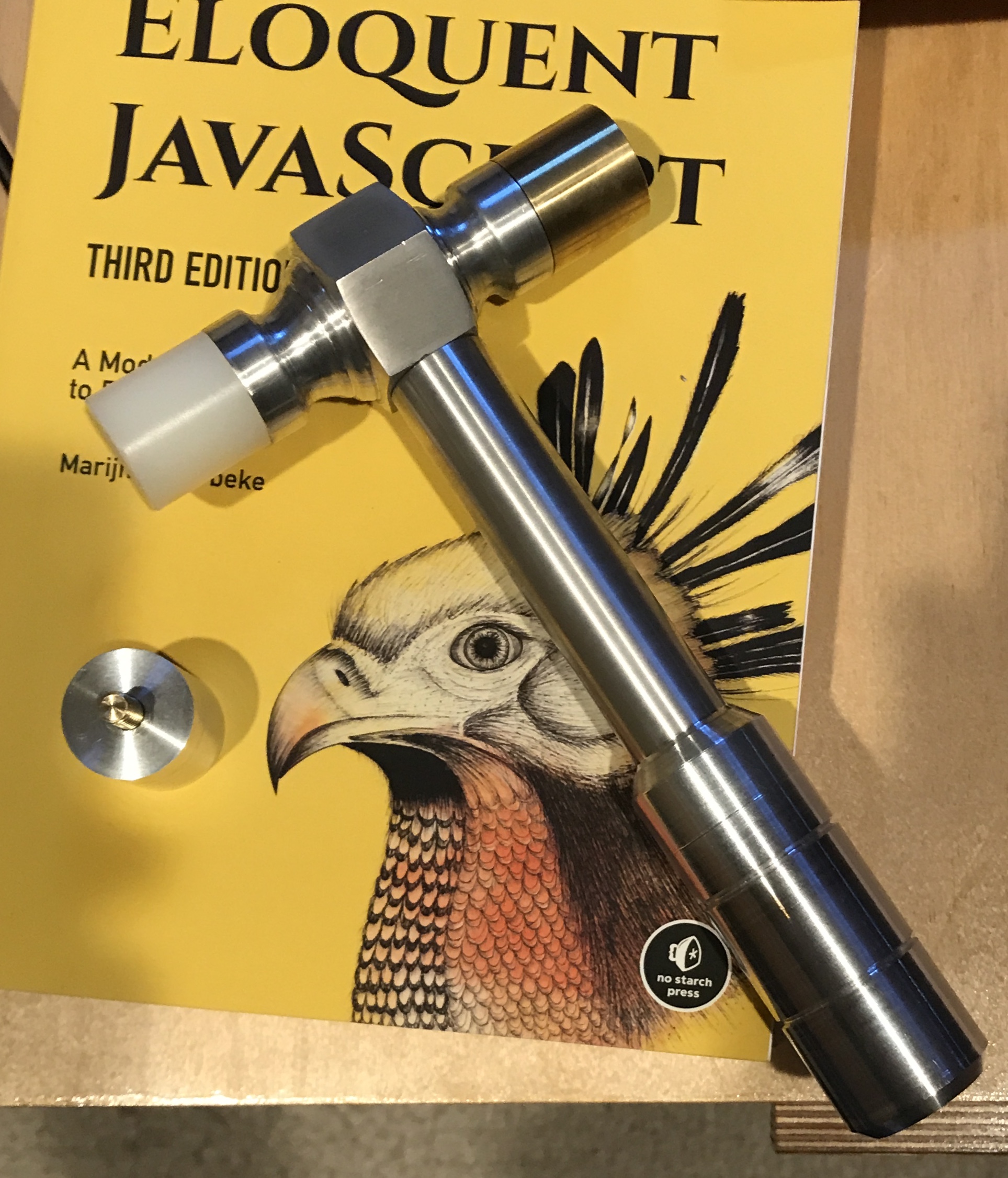
When the handle was installed it looked too big relative to the hex face of the head. It was put back in the lathe using soft jaws and a tailstock center. The narrow end was reduced to 0.86" diameter and this end was again sanded up to 1500 grit. The assembled hammer is shown below.
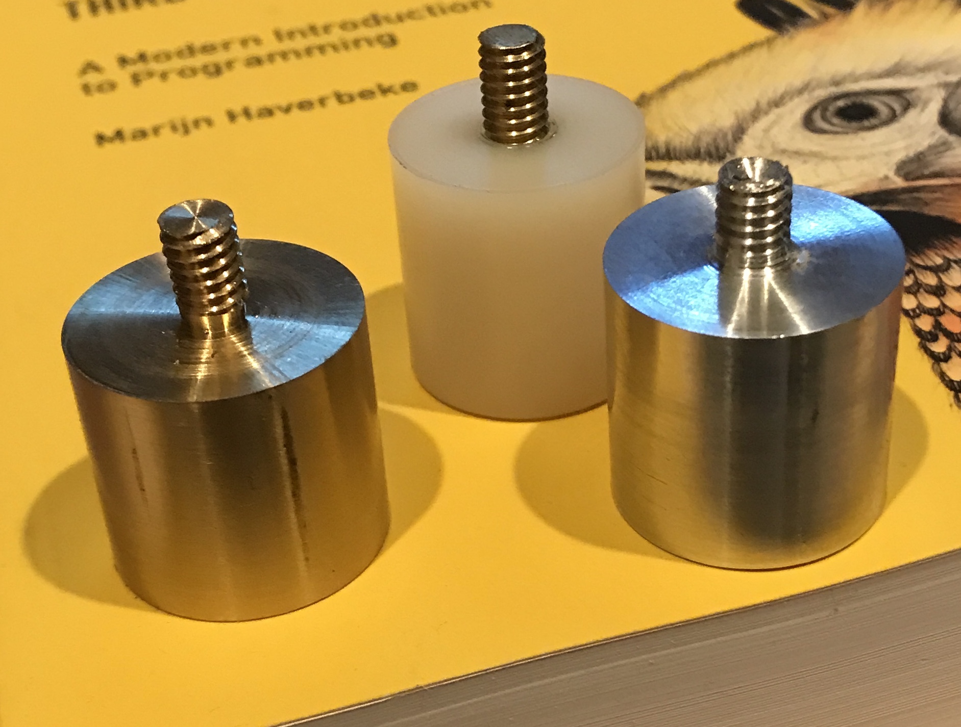
Worked on the faces with some success today even though the garage was quite cold. The brass face was cut first. A 5" length of brass was held in the three jaw with about 2" exposed. It was faced and then 1 1/2" was reduced to 1.00". The first 3/8" was further reduced to 0.25". The brass was parted off at 1 3/8". It was flipped in the chuck and the new end faced. The stub was threaded with a 1/4-20 die in the bench vise. I must have bent the stub somehow as it does not seat flush with the head. The aluminum face was made from the first head in a fashion similar to the brass. This stub was also threaded and is not bent! Finally the nylon was cut from 1" stock received. It had some text printed on the side so about 0.005" was removed to erase this text. I was unable to thread the nylon stub. The die just ground away the end and never cut threads. So the stub was removed and the nylon was drilled with a #7 drill and tapped 1/4-20. A length of brass was threaded for about 5/8" and cut off. The threaded rod was glued into the face with Loctite. This may be the approach used to salvage the brass face. The three faces at this stage are pictured below.
I noticed after multiple uses that the parting tool when used with the 3/8" cutter shim is significantly below center height!! This may be part of the reason for the challenges encountered during its use. I attempted to remedy this by placing a drill under the tool to add the needed extra shimming, but this was less than satisfactory. I will need to make a shim specifically for it.
The brass face was returned to the lathe after sawing off the threaded stub. The end was faced and a 1/4" hole was drilled 1/2" deep. The aluminum face went through the same process. Both faces were then placed in the vise and tapped 1/4-20. A 1/4" brass rod was put in the Sherline lathe and the 1/4-20 die was started after chamfering the end. The rod was then moved to the vise and threading continued for 1 1/4". Two nuts were put on the threaded end and 5/8" of thread was cut off with a saw. The nut on the cut off portion was removed over the cut end to clean up the threads. A second 5/8" length of thread was cut off and again a nut was used to clean up the cut threads. An end of the second threaded stub was chamfered. One threaded rod was screwed into the brass face and one into the aluminum face with the chamfered ends out. Both got a drop of Loctite on the threads prior to installing. After drying overnight the brass and nylon faces were screwed onto the hammer head. Only drilling and threading the end along with knurling the handle remain.
Knurled this afternoon on the South Bend lathe with the new knurling tool holder, I received yesterday. It was quite the comedy of errors. I decided to use the autofeed capability of the lathe. I loosened a screw at the end and engaged the gears turning the feed screw. After about ten minutes I was able to get the change gears engaged at an appropriate speed. It was fairly straightforward to engage the feed and to disengage it. That is until the handle popped off and a ball bearing rolled away. I was able to continue just by holding the handle in place. The handle was held in soft jaws and a tailstock live center was used for support. The new knurling tool holder was at the correct height when using the original washer for the lantern tool post. It took multiple passes with the knurling wheels before a deep enough knurl was formed. The compound had to be advanced (it was set at 91°) quite a bit farther (.050") than I expected. I guess that is to make up for all of the flex in the system. The ends of the knurl were then cleaned up by reducing the diameter by about 0.03".
The ball bearing was found, but the spring was not. The ball bearing was dropped in a hole in the handle opening so it won't get lost. I will need to go back to the South Bend rebuild to determine what type of spring to purchase.
Finally, the end of the handle was drilled with a #7 drill and tapped 1/4-20. The hole was drilled 1/2" like the rest of the holes for faces, but the aluminum face did not go in all the way. I put the aluminum face in the Sherline lathe with soft jaws and faced the end removing about 0.12". The threads were cleaned up with the die and the face was installed in the end of the hammer.
I am still considering reducing the diameter of the handle neck. Either a taper or just a smaller diameter. It just seems kind of big and clunky as it joins the head. Other than that it looks pretty nice.
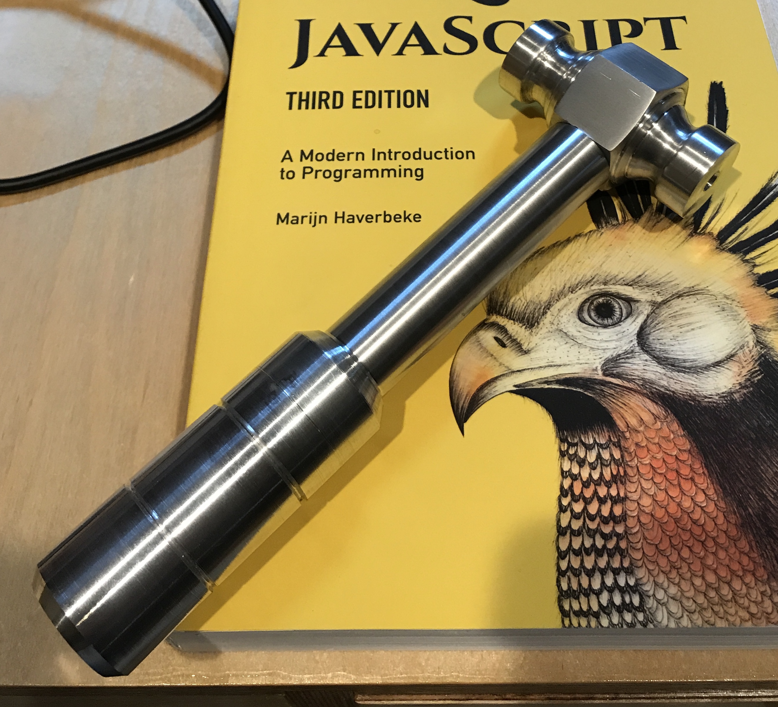
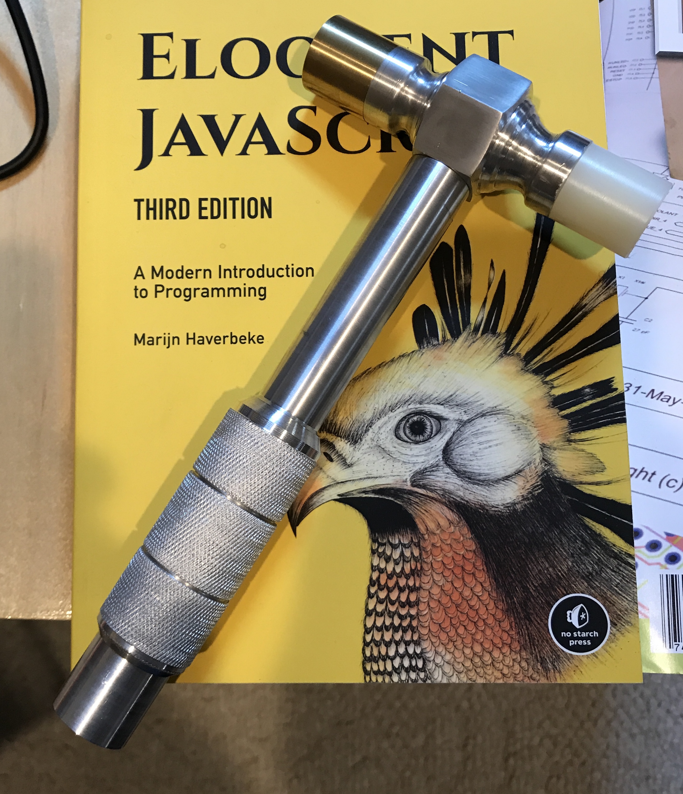
Decided to reduce the diameter of the shaft this morning. I attempted to use the taper attachment. I figured a 1.5° offset would give me a 3/32" smaller diameter at the head end with the taper extending the full 3.5" of the shaft. For some reason I could not get the cutter to follow the taper. Carriage movement was very tight. So I changed to just making a smaller diameter. I reduced the diameter to about 5/8". I then sanded up to 1500 grit. Finally, the taper from the knurled part to the new diameter was cleaned up using the compound slide. A final picture is included below.